Thursday 16 May 2013

Voiding the Warranty on a Digi Connect ME

I've always taken the approach in programming that if you're going to code for a platform, you had better understand the underlying technology. In Windows I've spent hours trawling through API specs, books and articles to get to grips with the lower levels that underpin the abstraction of the day. Whilst I sit up on top of all that, coding away in C#, I like to think I have a fairly deep understanding of the implications when I declare my new string;.
After a failed experiment in upgrading the Digi Connect ME (revision A) module to the Microsoft .NET Micro Framework (.NET MF) version 2.5, I decided to peel back the sticker and see what makes this module tick. My module was completely bricked, so I wasn't losing out on anything.
The Digi Connect ME is a 55MHz ARM 7 based .NET MF module. It has an RJ45 Ethernet port, a serial port and 5 GPIO ports. It's one of the simpler modules, and is appropriately low priced at around US $50 at the time of writing.
One of the first things I noticed when attaching a serial port to the module was this boot sequence (at 9600 baud):
image
Interestingly, it appears it is not the TinyCLR booting here, but another operating system 'NET+OS'. These modules are sold with two different platforms available: a NET+OS version; and a .NET MF version. One of the claims of Microsoft for the performance and efficiency of the .NET MF is that it does not actually require an underlying operating system (OS) to run - the .NET MF runs directly on the metal. It appears in this case though, that Digi has basically ported the .NET MF over the top of their existing embedded OS. What that probably means for development on the module is that any time you call a .NET MF managed method, under the hood you're just calling a wrapped NET+OS API.
If you switch the baud rate on the serial connection to 15,200, this is the boot sequence info:
DigiConnectMESerialOutputAt115k

Opening up the case reveals some more interesting details...
Opening the Chassis
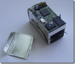
The case enclosing the DCME's innards is like an aluminium origami. You can easily slide your fingernail under the lip of any of the side flaps to prize them away from the main body. After a bit of unnecessary unfolding I discovered that actually all you need to do is:
  1. Peel away the sticker
     Dig Connect ME with No Sticker
  2. Open out the two aluminium tabs inside the RJ45 Ethernet port
    Dig Connect ME with RJ45 Tabs Open
  3. Unfold the under-plate's two sides
    On the bottom of the DCME is an aluminium plate covering most of the module, but exposing part of the module's PCB with the 20 pin header. This aluminium plate has two flaps that fold up and around the main body. Slide a fingernail inside the lip of the two side flaps enough to unhook them from the indented clip, then the whole plate should hinge down and away from the body of the module to reveal the whole PCB underneath. On mine the plate actually came away from the chassis due to 5 or 6 bends, but if you're careful this plate should remain attached.
    Dig Connect ME with under-plate Removed
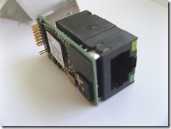
  4. Using a finger inside the RJ45 port, push the module out of its case altogether
    Dig Connect ME out of its Case Dig Connect ME out of its Case #2
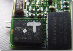
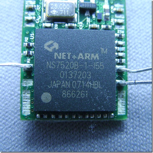
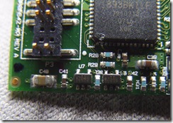
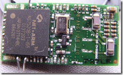
At this point the module does still power up and runs the small remnant of the OS that was left after the failed .NET MF upgrade... After the next bit though, there's not much chance I'll ever get this thing going again. These pictures show the chipset of the module once you clip the legs off the Ethernet port and remove it:
Oct2nd 08 015
Oct2nd 08 024
Oct2nd 08 031
Oct2nd 08 002  Oct2nd 08 035
Oct2nd 08 039
Oct2nd 08 040

Sunday 29 November 2009

LED Current Calculation

At first glance, the calculation of current to an LED seems simple – you need a resistor to limit the current flow to the LED so it doesn’t draw to much and burn out.

But what value of resistor do you need, and how do you work that out?

It turns out the answer gets quite complicated, mainly due to the forward voltage (Vf) property of an LED. Forward voltage, voltage drop, or Vf, indicates the voltage that the LED reduces the circuit voltage by when current is flowing through it. The value of Vf varies according to the current and the colour and quality of the LED. As a rough guide:

Red 1.7Vf
Green 2.2Vf
Yellow 2.1Vf
Blue 4.5Vf
White 3.4Vf

So what does that mean? Well basically it means that having an LED in your circuit will reduce the voltage in the circuit by the amounts shown above.

All of the voltages in the circuit are relative to the source voltage (Vs).

So if I have a 6V lantern battery (6Vs) and I hook up a green LED to it, suddenly there’s only 3.8V flowing through the rest of the components in the circuit.

To prevent the LED from burning out, you need to limit the amount of current that flows through it, usually to a maximum of between 20 and 30 milliamps (mA). The way you do that is by using a current-limiting resistor.

To calculate the required resistor value, you need a new voltage measurement: Vs –Vf, or Vresistor. Vs-Vf is the amount of voltage flowing through the ‘other components in the circuit’, namely the current-limiting resistor being used to restrict current flow through the LED and prevent damage occurring to it or the rest of the circuit.

LEDs are pretty flexible and they will happily light up with 5mA or even less. With smaller currents they will not be at their brightest and it will be much nicer to see them shining away with their maximum of 20mA or 30mA.

So as an example, lets say I have a red LED rated at a maximum 30mA and I want to light it up as brightly as possible with the full 30mA current supply. How would I calculate the resistor values required? To do that you need to go back to Ohm’s law and apply a bit of theory. Ohm’s law states that current is equal to voltage divided by resistance:

I = V/R

or in this case I = Vs-Vf / R

Lets take our 6V lantern battery and a red LED to start with. In the chart above the red LED’s Vf is shown as 1.7 volts. These values are all entirely hypothetical at this point - in reality the LED’s Vf will vary and the battery will not produce a stable 6V. We’re going to start needing some real numbers soon, but as a place to start let’s calculate the resistor you’d need using the chart values and the lantern battery’s theoretical 6V as a voltage source (Vs):

30mA = (6Vs – 1.7Vf) / R

so 0.03A = 4.3V / R

so R = 4.3 / 0.03

so R = 143.3333333333333

so R = 143 ohms

To get started calculating the actual resistor required, you first need to get a more accurate measure of the LEDs real forward voltage drop (Vf). The easiest way to do that is to take a battery and a resistor, hook up the LED and measure it with a multimeter.

The resistor value calculated with the theoretical values should be close enough that nothing will be damaged by using it to test the actual values. Different colour LEDs will vary their voltage characteristics based on the current passing through them so you’ll get inaccurate readings if you supply a different current in your tests. In this case I calculated 143 ohms, which I’ve added to the circuit using a 100 ohm and a 43 ohm resistor in series:

misc   LEDs 165

Gator clips are your friend when working with a lantern battery, so that’s how I’m hooking up my LED to test. If you had a 9V battery you’d be better off with a breadboard and a nine-volt battery connector.

Here are the measurements I’ve taken with the multimeter on this circuit:

143 ohm LED test 002 
Source voltage 6.34Vs
143 ohm LED test 008 
LED forward voltage 2.54Vf
143 ohm LED test 006 
Resistor voltage 3.79V

So the actual voltage of the source was wrong in theory and so was the forward voltage of the LED. If you’d used the theoretical calculated 143 ohms you would have been way off, supplying a mere 26.5mA to your LED and how dull that would be :). A much more accurate calculation can now be made with the real values:

R = Vs-Vf/I

so R = 6.34-2.54 / 0.03

so R = 3.8 / 0.03

so R = 126.6 ohms

so R = 127 ohms

That works out quite nicely because I happen to have a 100 ohm and a 27 ohm resistor in my kit here, so connected in series I can create a 127 ohm resistor. Here’s the LED now fulfilling its potential and shining away with a clear 30mA flowing through it:

127 ohm final LED config - filmstrip

I’m still blinking and seeing little LEDs from the image burned into my retina from looking it straight in the eye. A new moon has appeared on the ceiling, an angry red moon. In other words, the thing is on and it’s bright. It is also nice and cool and has remained cool for a few minutes. It should remain cool as it is within its operating parameters. I think I’ll leave it on all day and test that theory (and the staying power of the lantern battery).

For further reading I’d recommend taking a look at these links:

Technical Charts Showing LED Characteristics:
http://www.maxim-ic.com/appnotes.cfm/an_pk/3070

LED Resistor Calculator:
http://led.linear1.org/1led.wiz

Tuesday 13 October 2009

First Drill Press

Is it wrong to feel proud of a hole 0.5mm across?

Drill Press! 001

I bought my first drill press today and couldn’t help but feel a little glow at having drilled a hole in a piece of copper board destined to be my first home made printed circuit board (PCB). It even fits a transistor’s leg :).

Drill Press! 006

Sunday 2 August 2009

Using a Transistor as a Digital Switch

A basic requirement for digital electronics is to switch on a higher current device using the low current capable IO pins of a microcontroller.

A microcontroller is typically capable of outputting only a limited current of 90-200 milliamps (mA) across all of its IO pins. Even if you only have to light up a couple of bright LEDs that will not be enough and drawing more current than allowed could damage the microcontroller. To limit the current drawn whilst still supplying enough power to the controlled devices you need to use a device that can act as a digital switch. A transistor can fill this role, drawing only a few milliamps from the microcontroller whilst the controlled devices draw as much as they require.

There are a several types of transistors which can allow you to switch on or off anything from LEDs to motors. The decision for which transistor to use depends on how fast the switch needs to be flipped, and how much power will flow through it.

TO-92 Packaged BC547 TransistorBipolar Junction Transistor (BJT)
A BJT transistor such as the NPN BC547 shown on the right can function as a digital switch. When a small amount of power is supplied to its base (middle leg), power is allowed to flow between its collector (left leg) and emitter (right leg). When the base is grounded no power can flow between collector and emitter.

There are two types of BJT transistor, NPN and PNP. NPN is far more widely used and in the majority of cases NPN is a better choice. The circuit symbols are shown below:
Transistors and Digital IO - PNP vs NPN

Here is a simple circuit demonstrating an NPN transistor being used to switch on an LED:
Transistors and Digital IO 

The circuit uses the 3.3V supply from the microcontroller’s IO pin, limited to 3.3mA by the 1K resistor, to allow the 5V supply, limited to 50mA by the 100 ohm resistor, to flow through the LED.

I built the circuit using the Digi Connect ME microcontroller and a breadboard:
Digi Development Board

The gator clip wires shown on the left connect up the Digi development board’s 5V supply to the breadboard’s left hand power rail. The white wire connects the first IO pin of the microcontroller (GPIO1) to the breadboard’s 1K resistor at the base of the BC547 transistor:

Breadboard Showing Transistor Circuit

If you have to switch higher current loads, say to drive a motor or a pump, different types of transistors may be applicable. The BC547 has a maximum current throughput of 100mA, so it’s only suitable for small loads such as the driving this LED. In particular Field Effect Transistors (FET) may be a better choice for many higher current robotics applications.

The Microsoft .NET Micro Framework (.NET MF) C# code used to test out the circuit is here:
http://purerobotdigiconnect.codeplex.com/SourceControl/changeset/view/29696#691604

Monday 13 October 2008

Digi Connect ME JumpStart Kit Hardware Emulation + Demo Code

Here is a small demo application running on a Digi Connect ME JumpStart kit, and an emulator of the kit:

I've started a new open source project for Digi Connect ME sample code, hosted on the TFS servers at CodePlex:

http://www.codeplex.com/PureRobotDigiConnect 

The Pure Robot - Digi Connect ME project demonstrates the basics of interaction with the Digi Connect ME module, as well as emulation of the JumpStart kit hardware.

Emulating Hardware
One of the main features of this project is the Digi Connect ME JumpStart kit emulator. This was an interesting exercise for me since Digi do not supply their own emulator along with the kit and I've never attempted to build an emulator before. I've created one in the solution, in a project named PureRobot.Emulators.Digi.ConnectME.JumpStart. The code is in a beta stage: it's ready to look at with the LightFun sample code being discussed; however the serial emulation UI is not complete so the other sample projects in the solution may not work as expected yet.

The emulation features of the Microsoft .NET Micro Framework (.NET MF) are very easy to work with. Essentially all you need is a few lines of .NET code, an XML configuration file and some kind of UI. You can then execute your .NET MF code against the emulator and (in theory) see the same results as you would on the actual hardware.

I've made a basic attempt at defining the hardware in the emulator XML configuration file:

http://www.codeplex.com/PureRobotDigiConnect/SourceControl/FileView.aspx?itemId=13592&changeSetId=4771

This file outlines the Input / Output (IO) capability of the Digi Connect ME module, and the memory characteristics as defined in the documentation:

Processor: 55MHz NS7520 (Digi Part no. NS7520B-1-I55)
Memory: 2 MB of Flash, 8 MB of SDRAM
IO: 5 GPIO pins, TTL (CMOS 3.3V) serial

For the user interface I used an image of the JumpStart kit board and added some overlaid bitmaps for the LEDs in the on state.

The emulator framework provides a nice set of objects to listen out for GPIO state changes. The only complexity in the UI code is that IO events will occur on another thread, so you need to synchronize with the UI thread before modifying the Windows Forms components to represent changes. When I first tried this, I used the InvokeRequired/BeginInvoke pattern of Windows Forms controls, but found the performance sucked. Instead I went for a synchronized set of integer variables which are modified by the IO thread using .NET thread synchronisation objects, then read on a timer from the UI thread - this seems to give a more realistic emulation experience.

The code for the UI form is here:

http://www.codeplex.com/PureRobotDigiConnect/SourceControl/FileView.aspx?itemId=159650&changeSetId=4771

Running the Demo Code
To run the sample code:

  • Download the Visual Studio 2005 source and open the solution
    • You might have to cancel a few dialogs that attempt to access the source control server, then choose to 'Permanently remove source control association bindings'
  • Build the solution
    • When you build the solution the emulator will be added to the registry
  • Open the Project Properties of PureRobot.Digi.ConnectME.JumpStart.LightFun -> Micro Framework tab, and set the Transport to Emulator and the Device to 'PureRobot.Emulators.Digi.ConnectME.JumpStart'
  • Set the PureRobot.Digi.ConnectME.JumpStart.LightFun to the startup project
  • Run (hit F5)
    • If everything has been successful you should see the lights flashing away on the emulator application as they do in the video above.

Please feel free to play with the code and if you have any bugs, problems or improvements please don't hesitate to contact me through comments to this post or through the CodePlex site.

Wednesday 17 September 2008

Voltage Regulation

Voltage RegulatorA common requirement for powering a microcontroller based circuit is to regulate voltage to a steady level, protecting the sensitive equipment from fluctuations in power.

One of the simplest devices that can be used to achieve this result is a voltage regulator, such as the Sipex SPX1117U shown to the right.

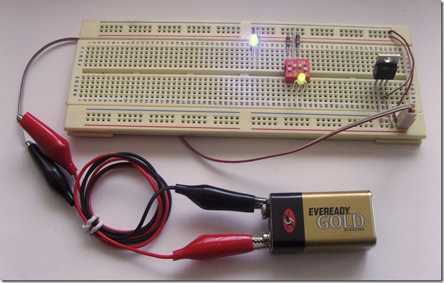
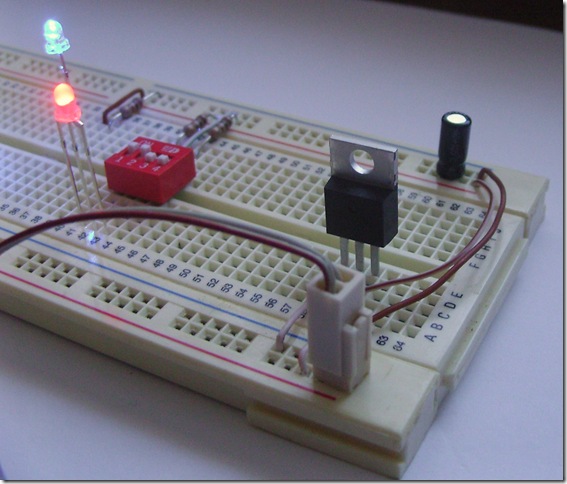
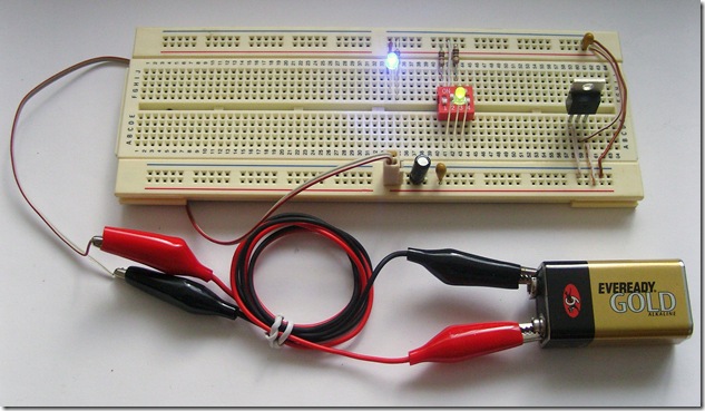
Using the SPX1117U (the 3.3 volt variant of the SPX1117 range), I have hooked up a small circuit on the breadboard to demonstrate the process. The circuit below consists of the following components:

  • 9V Battery
  • Gator clip wires
  • Home made power jack - two strips from a ribbon cable crimped onto a two pin socket
  • Assorted jumper wires - mainly borrowed from a spare bit of CAT5 cable
  • An SPX1117U voltage regulator
  • Three 100 ohm resistors (Brown, Black, Brown)
  • A bright blue LED
  • A dull three colour LED
  • A DIP switch block used to control the colour of to the three colour LED

Voltage Regulation 012 

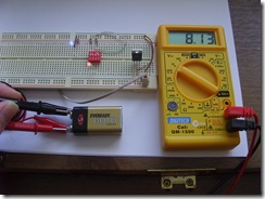
You can see the voltage output from the 9 volt battery, 8.13 volts:

Voltage Regulation 013

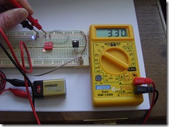
And the voltage being sourced from the SIPEX SPX1117U voltage regulator, a perfect 3.3 volts:
Voltage Regulation 014


The resistors are required here to protect two components: the LEDs which have a maximum current of around 30 milliamps and the voltage regulator itself which can supply a maximum current of 800 milliamps. The brightness of the LEDs will be determined by several factors to do with the quality of the material they were constructed with and the amount of current passing through them. The current flowing through the LEDs is limited by two 100 ohm resistors protecting each LED. The choice of 100 ohm resistors was somewhat arbitrary, being enough to ensure a small current is supplied so that the LEDs will light up brightly without overburdening the voltage regulator or burning out the LEDs.

Improving the Stability
Voltage Regulator with Capacitor 018The circuit above is fine for LEDs, but if you want to power something which requires a steadier voltage you'll need some additional components. According to the SPX1117U documentation, an output capacitor with a minimum value of 2.2uF but recommended 100uF will make the output stable.

In order to increase the output voltage stability, I've added a 100uF aluminium capacitor to the circuit. It is placed across the 3.3 volt output power rail:

Voltage Regulator with Capacitor 013

In simplified circuit diagram form, this is the above circuit, including the stabilizing capacitor:

Stabilized

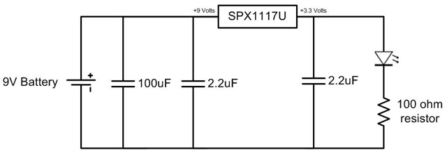
The use of capacitors as filtering and decoupling agents is especially important when one power source will be used for both sensitive components like microcontrollers and for rough components like motors. In the circuit above the capacitor is purely used for stabilizing the power output from the voltage regulator, however a more robust design to protect a sensitive circuit could be implemented like this:

Voltage Regulator with Filter   Decoupling Capacitors 004 Voltage Regulator with Filter   Decoupling Capacitors 006Voltage Regulator with Filter   Decoupling Capacitors 008

Because of the different electrical characteristics and capacities that different materials allow for, a 100uF aluminium capacitor is used here as a filter and two 2.2uF tantalum capacitors for decoupling.

The circuit can be simplified into the diagram below:

Decoupled Filtered

This power supply circuitry can provide a stable platform for a simple robot, allowing the microcontroller to enjoy a steady voltage level whilst the other components of the robot introduce spikes and drains on the supply as they grind their way across the deserts of Mars or are picked up and hurled by a toddler.

Note: Thanks to the kind people on Electro Tech Online forums for helping me understand the issues surrounding LED current calculations, which I’ll cover further in a later post.